-
-

Clique na imagem para ampliar.
|
|
Compartilhe
|
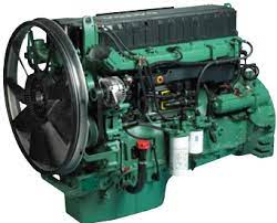
Workshop Manual Group 30 Electrical system TAD950VE, TAD951VE, TAD952VE TAD1250VE, TAD1251VE, TAD1252VE
Group 30 Electrical system
Industrial engines
TAD950VE, TAD951VE, TAD952VE
TAD1250VE, TAD1251VE, TAD1252VE
Contents
Safety rules............................................................ 3
General information .............................................. 4
About this Workshop Manual ............................... 4
Spare parts .......................................................... 4
Certified engines .................................................. 4
Repair instructions................................................ 5
Our common responsibility................................... 6
Tightening torques ............................................... 6
Special tools ......................................................... 7
EMS 2 - ?Engine Management System? .............. 8
General information .............................................. 8
CAN - Controller Area Network ............................. 8
CIU - Control Interface Unit .................................. 8
DCU - Display Control Unit ................................... 9
DU - Display Unit ................................................. 9
Fuel control ........................................................ 10
Calculation of fuel quantity ................................. 10
Altitude correction .............................................. 10
Diagnostic function ............................................ 10
Component location ........................................... 11
TAD950-952VE .................................................. 11
TAD1250-1252VE .............................................. 13
Component description ...................................... 15
Starter motor ...................................................... 15
Alternator ........................................................... 15
Unit injectors ...................................................... 16
Speed sensor crankshaft ................................... 16
Speed sensor camshaft ..................................... 16
Boost pressure/temperature sensor ................... 17
Oil pressure sensor ............................................ 17
EGR................................................................... 17
Oil level/temperature sensor .............................. 18
Air filter pressure/temperature sensor................. 18
Crankcase pressure ........................................... 18
Monitor, water in fuel .......................................... 19
Monitor, coolant level ......................................... 19
Engine control unit, EMS 2 ................................ 20
Coolant temperature sensor ............................... 21
Monitor, piston cooling ....................................... 21
Fuel pressure sensor ......................................... 21
Repair instructions.............................................. 22
General advice on working with EMS engines .... 22
Electric welding .................................................. 23
Changing the engine control unit ........................ 24
Reprogramming a control unit............................. 25
Programming an empty control unit .................... 26
Fault tracing of cables and connectors ............... 27
Joining electrical cables for connectors.............. 29
Fault tracing of the starter motor and windings ... 31
Malfunctions ........................................................ 32
Fault code information........................................ 32
FMI table / SAE standard .................................. 33
Manual fault tracing in bus cables ...................... 36
Alternator fault finding ........................................ 37
Diagnostic Trouble Codes .................................. 39
MID 128, PID 45
Inlet air heater status ......................................... 39
MID 128, PID 94
Fuel pressure ..................................................... 42
MID 128, PID 97
Water in fuel....................................................... 48
MID 128, PID 98
Oil level.............................................................. 52
MID 128, PID 100
Oil pressure ....................................................... 55
MID 128, PID 105
Boost temperature ............................................. 61
MID 128, PID 106
Boost pressure................................................... 67
MID 128. PID 107
Air filter pressure (only TAD1250-1252VE) ......... 73
MID 128, PID 110
Coolant temperature ........................................... 78
© 2006 AB VOLVO PENTA
We reserve the right to make modifications without prior notice.
Printed on environmentally compatible paper.
MID 128, PID 111
Coolant level ...................................................... 86
MID 128, PID 153
Crankcase pressure ........................................... 90
MID 128, PID 158
Battery voltage................................................... 96
MID 128, PID 172
Inlet air temperature (TAD1250-1252VE) ............ 98
MID 128, PID 175
Oil temperature .................................................105
MID 128, PID 190
Engine speed ....................................................110
MID 128, PPID 3
Starter output failure .........................................111
MID 128/144, PPID 4
Starter input failure ............................................115
MID 128, PPID 6
Stop input .........................................................117
MID 128, PPID 8
Piston cooling pressure .....................................119
MID 128, PPID 19
Internal EGR status ..........................................122
MID 128, PPID 98
Engine sync acknowledge .................................127
MID 128/144, PPID 132
Throttle input request failure, DCU/CIU .............128
MID 128, SID 1-6
Unit injector # 1-6 ..............................................132
MID 128, SID 21
Speed sensor, camshaft ...................................138
MID 128, SID 22
Speed sensor, crankshaft .................................143
MID 128/144, SID 231
Communication fault J 1939 ..............................148
MID 128, SID 232
5 Volt DC supply current ...................................152
MID 128, SID 240
Program memory fault.......................................154
MID 128, SID 250
Communication fault J1587/J1708 ....................155
MID 128/144, SID 253
Calibration memory, EEPROM, fault .................157
MID 128/144, SID 254
Controller error ..................................................158
Fuel bleeding pump (no fault code,
only TAD950-952VE) ........................................160
Engine protection ..............................................161
Wiring diagrams.................................................162
Electrical diagram EMS2
TAD950-952VE ................................................162
TAD1250-1252VE ............................................163
Wiring diagram DCU ..........................................164
Wiring diagram CIU ...........................................165
Technical data ....................................................166
Monitor, water in fuel .........................................166
Sensor, fuel pressure ........................................166
Speed sensor, crankshaft/camshaft ..................166
Sensor, oil pressure ..........................................166
Combination sensor,
boost pressure/temperature...............................166
Sensor, coolant temperature .............................166
Monitor, coolant level ........................................167
Alternator ..........................................................167
Starter motor .....................................................167
Sensor, carnkcase pressure .............................167
Combination sensor, oil level/temperature .........167
Monitor, piston cooling ......................................167
Combination sensor,
air filter pressur/temperature .............................167
Index ...................................................................168
References to Service Bulletins ........................170
IDIOMA INGLÊS
176 Págs.
Envio por link para download.
|